

This will be the last blog entry, before we finally start covering tyres. This time we’re going to cover the latest steering system. Add force and torque distributions afforded by UltraChassis. We’ll also format the brake pressure to match our other cars and add a couple other little bits.
Steering System
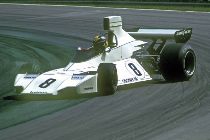
Fig.1, An example of the real life steering system, in action (Image Source: Motor–Sport™).
What exactly does the new steering system change? It’s essentially another, more powerful way to define the steering properties.
Inner geometry freedom
The steering system allows complete freedom in what the inner steering linkages do as you apply lock. This opens up the possibility of non-linear steer ratios for cars that have them. The C6.R GT2 is one such example of a vehicle with non-linear steering. It also allows for more uncommon steering geometries, such as those employed in go-karts, which rotate around a point and move around 3 separate dimensions. Typical rack and pinion systems generally only move laterally, so for the majority of cars this is not going to make an Earth shattering difference.
This is all done through SteeringInnerTable entries, which have the syntax as follows:
SteeringInnerTable=(<FL_STEERING_X>,<FL_STEERING_Y>,<FL_STEERING_Z>):(<FR_STEERING_X>,<FR_STEERING_Y>,<FR_STEEERING_Z>)
Each entry between “()” brackets are the X,Y,Z co-ordinates (relative to the relevant sub-body), of the inner steering joints. : denotes the next step in the chain, which alternates from left to right wheels. How many entries you have dictates how many steering points you have. You need at least 4 bracketed entries (4×3=12 total numbers). The first 2 will always be at maximum left lock. The final 2 entries will represent the inner locations of the [Constraint]s, “FL_STEERING” & “FR_STEERING” at maximum right steering lock @ LocalOffsetA. To set these properly, you need to know or at least estimate the maximum steering rack displacement. The constraints central location can be obtained from the ultrachassis.ini file, if you use the spreadsheet, these are done automatically if you supply basic information.
The steering shaft position, as it relates to the steering rack, is now split into 2 parts and adjustable. Left obviously forms the base for the left wheel, and right for the right wheel. Most cars only have 1 steering shaft, so they should generally have same values:
SteeringShaftBaseLeft=(<LeftShaft_X>,<LeftShaft_Y>,<LeftShaft_Z>) // Location of steering shaft relative to steering arm
SteeringShaftBaseRight=(<RightShaft_X>,<RightShaft_Y>,<RightShaft_Z>)
There is also a steering shaft axis variable, which is essentially the inclination of the steering shaft into the steering rack.
SteeringShaftAxis=(<AxisX>,<AxisY>,<AxisZ>)
You can manipulate the steering through special overrides in the .HDV.
The custom steering can also be used in special instructions, in case you need to change the inner geometry as well. The syntax is almost the same as when you put it in the HDV [CONTROLS] section, except you do NOT reuse SteeringInnerTable to add more entries. Instead you can concatenate with the backslash-plus (i.e. \+) combination. In other words, the above HDV changes put into a special instruction could look like:
SteerLockSpecial(0,,,"SteeringShaftBaseLeft=(0.0,-0.07571448,-0.616415")
SteerLockSpecial(0,,,"SteeringShaftBaseRight=(0.0,-0.07571448,-0.616415)")
SteerLockSpecial(0,,,"SteeringShaftAxis=(0.0,0.0,1.0)")
SteerLockSpecial(0,,,"SteeringInnerTable=(0.464472,-0.065,-0.616415045):(-0.301488,-0.065,-0.616415)")
SteerLockSpecial(0,,,\+"(0.38298,
-0.065,-0.616415):(-0.38298, -0.065,-0.616415045)")
SteerLockSpecial(0,,,\+"(0.3014879,-0.065,-0.616415045):(-0.464472,-0.065,-0.616415)")
Slightly more accurate forces at the wheel
The old steering system had a slight simplification to it. The new system is not going to revolutionize your vehicle, but the forces going through the wheel are more accurate. The difference is probably only in the realm of 1-2% for most cars. In the end, the steering forces are a direct result of the suspension geometry, tyre properties and forces acting upon them. They are a direct link to the physics.
The end result is that the old steering variables:
NominalMaxSteeringTorque=7.3
TurnsLocktoLock=1.8
SteerLockRange=( 10 , 1 , 14 )
SteerLockSetting=13
Are replaced by:
NominalMaxSteeringTorque=7.3
TurnsLockToLock=1.8
SteeringShaftBaseLeft=(0,0.265912,-0.378279)
SteeringShaftBaseRight=(0,0.265912,-0.378279)
SteeringShaftAxis=(0.17365,0,0.98481)
SteeringInnerTable=(0.32605,0.26,-0.377236):(-0.39395,0.26,-0.377236)
SteeringInnerTable=(0.39395,0.26,-0.377236):(-0.32605,0.26,-0.377236)
SteerLockCaption="WHEEL RANGE (LOCK)"
SteerLockRange=(22.192,0,9)
SteerLockSpecial=(0,"240 ","(8.2) deg","TurnsLockToLock=0.666667;SteeringFraction=0.37037")
SteerLockSpecial=(1,"270 ","(9.2) deg","TurnsLockToLock=0.75;SteeringFraction=0.416667")
SteerLockSpecial=(2,"310 ","(11) deg","TurnsLockToLock=0.861111;SteeringFraction=0.478395")
SteerLockSpecial=(3,"360 ","(12) deg","TurnsLockToLock=1;SteeringFraction=0.555556")
SteerLockSpecial=(4,"380 ","(13) deg","TurnsLockToLock=1.055556;SteeringFraction=0.58642")
SteerLockSpecial=(5,"450 ","(15) deg","TurnsLockToLock=1.25;SteeringFraction=0.694444")
SteerLockSpecial=(6,"540 ","(18) deg","TurnsLockToLock=1.5;SteeringFraction=0.833333")
SteerLockSpecial=(7,"630 ","(22) deg","TurnsLockToLock=1.75;SteeringFraction=0.972222")
SteerLockSpecial=(8,"648 ","(22) deg","TurnsLockToLock=1.8;SteeringFraction=1")
SteerLockSetting=8
Force & Torque Distributions
For this next part, you’ll probably want blueprints. Such as these in the case of the BT44B:
Fig.2, Scribbled on BT44 ‘blueprints’ Original Source: DrawingDatabase.com
To determine measurements, simply count the pixels of a known measurement. I used the wheelbase, in this instance. In this diagram, I’ve overlaid various points of interest, using the parameters of the car. The first thing you might note, the front wing aero center is actually outside of any physical dimension of the car. This was not an error of the original author (remember from my first blog, I did not create the original vehicle). Rather it’s a mathematical trick to enable a more accurate aero center of pressure, or downforce balance, shift due to pitch changes. The rest shouldn’t look too strange. Aerodynamics is beyond today’s blog, but I will come back to it, at some point in the future.
The first “ForceDistrib” is that of the fuel tank. You may remember that the BT44’s one is rather complex, ‘divided’ into 3 parts surrounding the driver. I’ve done my best to outline approximately where they actually are below:
Fig.3, Approximation of fuel tank layout.
Using a paint program, the magic wand selection tool displays the ‘pixel area’. The side tanks give about 96,977 square pixels, while the mid tank is 45,249 sq pixels.
Multiplied by the vertical height of 160 pixels, that gives us 96977*160+45249*160=22756160 cubic pixels. The conversion for the image is ~1.9975 millimeters per pixel. The eagle eyed among you might have noticed that I only included one ‘side tank’ in the equation. Why? Because these tanks are actually triangular shaped (when viewed from the front/rear), therefore they basically take up half the volume of a cuboid, so if you use the full height, you only need to include one in your calculation. Of course Liters as a unit, is defined as decimeters cubed, as in a cube of 10cm length.
Multiplied by the vertical height of 160 pixels, that gives us 96977*160+45249*160=22756160 cubic pixels. The conversion for the image is ~1.9975 millimeters per pixel. The eagle eyed among you might have noticed that I only included one ‘side tank’ in the equation. Why? Because these tanks are actually triangular shaped (when viewed from the front/rear), therefore they basically take up half the volume of a cuboid, so if you use the full height, you only need to include one in your calculation. Of course Liters as a unit, is defined as decimeters cubed, as in a cube of 10cm length.
So the drawing results in a volume of about:
(96977*160+45249*160)*(1.9975/100)^3 = 181.37 Litres, pretty damn close to the real things’ claimed 186L. The ‘100’ number is really just a conversion from millimeters to decimeters. According to these measurements, the tank is also about 1.4m long. However, when you try to take a weighted average, due to the unusual shape, you may assume something like 1.1m. This is done to reduce the twisting torques on the individual sub-bodies. Because we’re splitting them into 2 sub-bodies, you need to use half the length of this as the basis (when you divide a uniform object in 2, their CG’s are spaced at 1/2 the length of the original object). We’re effectively dividing the fuel into 2 parts, the CG of each is then offset from the original CG. Because the fuel tank is mostly ahead of the CG, I will go with about 55% on the front sub-body. 1.1*0.5*(1-0.55) gives us a forward offset of 24.75cm. For the rear, with a split of 45%, it would be 1.1*0.5*(1-0.45), 30.25cm aft.
FuelTankForceDistrib=(0.55:front_subbody:(0.0,0.0,-0.2475), 0.45:rear_subbody:(0.0,0.0,0.3025))
Because the front wing is clearly ahead of the front wheels. There is no need for any offsets or complex sub-divisions. 100% of the force should go through the front sub-body:
[FRONTWING]
FWForceDistrib=(1.0:front_subbody)
Same for the rear:
[REARWING]
RWForceDistrib=(1.0:rear_subbody)
The ‘fenders’ are used as additional aero points. The ‘Left’ fender placed between the front wheels. So we’ll give it all to the front sub-body.
[LEFTFENDER]
FenderForceDistrib=(1.0:Front_subbody)
Under “[RIGHTFENDER]”, we see that it’s placed far behind the front axle, approximately at the rear axle. The parameter that shows this is FenderCenter=(0,0,2.3876).
[RIGHTFENDER]
FenderForceDistrib=(1.0:Rear_subbody)
We’ll put 55% of the aero on the front body.
BodyAeroForceDistrib=(0.55:front_subbody:(0,0,-0.45),0.45:rear_subbody:(0,0,0.55))
[DIFFUSER]
Technically, this car did not have a diffuser, nor was ground effects an exploited aerodynamic necessity in racing. However, just because they did not understand it’s potential, does not mean it didn’t exist. The car had a flat bottom, and it ran with some rake. Inevitably, it was going to produce *some* ground effect. The car was also considered a full ground effect precursor. We’re not talking huge numbers here, obviously, but we should think about where to place the sub-body offsets. In the prior diagram, I had also taken a ‘best guess’ kind of approach for the diffuser. Keeping in mind that some height sensitivity had already been attributed with the front wing. To simplify this, we’re going to assume that the diffuser pressure distribution is even. The length I used is 1.928m, halved, gives us a gap between sub-bodies of 0.964m. If I distribute 60% of the force to the front, this requires a foreward offset of 0.964*(1-0.6)=0.3856m.
DiffuserForceDistrib=(0.6:front_subbody:(0,0,-0.3856),0.4:rear_subbody:(0,0,0.5784))
[DRIVELINE]
The engine, clutch, gearbox and differential torques can now also be apportioned between the bodies. Being mid-engine, and a structural component, it will overwhelmingly have a direct influence on the rear of the car. It’s hard to know what to use without doing some kind of structural analysis, but using it’s position in the wheelbase is probably a good starting point. The numbers I came up with are as follows:
EngineTorqueDistrib=(0.182:front_subbody,0.818:rear_subbody)
ClutchTorqueDistrib=(0.07:front_subbody,0.93:rear_subbody)
GearboxTorqueDistrib=(1.0:rear_subbody)
DifferentialTorqueDistrib=(1.0:rear_subbody)
Some last little HDV bits
Pushrod connections
Again, the enhancement here is aimed at flexibility and accuracy. In reality, the geometry is that of a pull-rod layout on the front end. And we can’t fully simulate this. By placing the pushrods as upright as possible, around on the kingpin axis, we ensure minimal change in motion ratios or wheel rates.
[FRONTLEFT]
Old:
PushrodSpindle=(0.006497906,-0.375634207131652,-0.0322502269795518)
PushrodBody=(0.006497906,0.42436579286835,-0.0322502269795518)
New:
PushrodOutboard=(1:FL_SPINDLE:(0.111927,-0.11675,-0.01))
PushrodInboard=(1:Front_Subbody:(0.665,0.47,-0.4872))
1: refers to force distributed to that sub-body. FL_SPINDLE is the sub-body to which that force is applied. (0.111927,-0.11675,-0.01) is the position offset, relative to the center of that sub-body. Put another way the syntax is:
<ForceDistribution>:<Body>:(<OffsetX>,<OffsetY>,<OffsetZ>)
[REARLEFT]
We’re replacing the old pushroad format of:
PushrodSpindle=(-0.01,-0.2,0)
PushrodBody=(-0.01,0.3,0)
With the new:
PushrodOutboard=(1:RL_SPINDLE:(-0.002793,-0.158054,-0.1))
PushrodInboard=(1:Rear_Subbody:(0.55,0.485,0.2104))
Again, the new parameters allows you to specify which rigid body the ‘pushrods’ attach to. While it previously forced one end to the spindle and the other to the body.
[CONTROLS]
For consistency with other vehicles, the “BRAKE PRESSURE” caption will be overridden by “MAX PEDAL FORCE”. Essentially, it is displayed in this manner to give the user an idea of how much brake pedal force is needed for that particular vehicle. This is useful if you have an adjustable load cell. The new values are equivalent to the old behavior for this car.
New:
BrakePressureCaption="MAX PEDAL FORCE"
BrakePressureRange=(0.555556,0.011111,41)
BrakePressureSpecial=(0,50," kgf (56%)",)
BrakePressureSpecial=(1,51," kgf (57%)",)
BrakePressureSpecial=(2,52," kgf (58%)",)
BrakePressureSpecial=(3,53," kgf (59%)",)
BrakePressureSpecial=(4,54," kgf (60%)",)
BrakePressureSpecial=(5,55," kgf (61%)",)
BrakePressureSpecial=(6,56," kgf (62%)",)
BrakePressureSpecial=(7,57," kgf (63%)",)
BrakePressureSpecial=(8,58," kgf (64%)",)
BrakePressureSpecial=(9,59," kgf (66%)",)
BrakePressureSpecial=(10,60," kgf (67%)",)
BrakePressureSpecial=(11,61," kgf (68%)",)
BrakePressureSpecial=(12,62," kgf (69%)",)
BrakePressureSpecial=(13,63," kgf (70%)",)
BrakePressureSpecial=(14,64," kgf (71%)",)
BrakePressureSpecial=(15,65," kgf (72%)",)
BrakePressureSpecial=(16,66," kgf (73%)",)
BrakePressureSpecial=(17,67," kgf (74%)",)
BrakePressureSpecial=(18,68," kgf (76%)",)
BrakePressureSpecial=(19,69," kgf (77%)",)
BrakePressureSpecial=(20,70," kgf (78%)",)
BrakePressureSpecial=(21,71," kgf (79%)",)
BrakePressureSpecial=(22,72," kgf (80%)",)
BrakePressureSpecial=(23,73," kgf (81%)",)
BrakePressureSpecial=(24,74," kgf (82%)",)
BrakePressureSpecial=(25,75," kgf (83%)",)
BrakePressureSpecial=(26,76," kgf (84%)",)
BrakePressureSpecial=(27,77," kgf (86%)",)
BrakePressureSpecial=(28,78," kgf (87%)",)
BrakePressureSpecial=(29,79," kgf (88%)",)
BrakePressureSpecial=(30,80," kgf (89%)",)
BrakePressureSpecial=(31,81," kgf (90%)",)
BrakePressureSpecial=(32,82," kgf (91%)",)
BrakePressureSpecial=(33,83," kgf (92%)",)
BrakePressureSpecial=(34,84," kgf (93%)",)
BrakePressureSpecial=(35,85," kgf (94%)",)
BrakePressureSpecial=(36,86," kgf (96%)",)
BrakePressureSpecial=(37,87," kgf (97%)",)
BrakePressureSpecial=(38,88," kgf (98%)",)
BrakePressureSpecial=(39,89," kgf (99%)",)
BrakePressureSpecial=(40,90," kgf (100%)",)
BrakePressureSetting=31
 (1)")
 Screenshot 2023.04.06 – 16.25.34.09 (2)")
