
We have released a simplified version of our physics tool for you to use in mod making and with flexible chassis. This tutorial will show the process of creating car files using it.
To start with an example of converting the Skip Barber to have a flexible chassis, the same basic process applies to any vehicle, using the skip barber is just our example.
It’s recommended that you use WinMerge or similar software to compare your file with our file to check for any mistakes and/or changes made.
1) Run rF2 in developer mode, load up a track with the Skip Barber (or vehicle of choice) selected. Then exit out of rF2 dev mode. It will have created a simple conversion of the PM file to a pTool-like INI file in \UserData. Using the skip barber example, the filename will be “SKIPBARBER_SUSP (converted from pm).ini”. Note that the converter has updated the mass and inertia of the main body (from the HDV data minus the other bodies), the mass of the fuel tank (always converts to 0.5 from PM files), and the pitch inertia of the wheels (from the SpinInertia). Open this file and save a copy into your \pTool folder inside rFactor, let’s just call it “SkipBarber_Chassis.ini” as opposed to the old “SkipBarber_susp.pm” file.
2) For this next part it’s easier to use pTool, but we’ll cover the text editor approach first, either should give identical results but you can go either way (alternate pTool method to follow):
a)i) Text Editor: Make an additional copy of the rigid body entry called “BODY”, and replace the names with two bodies called “FRONT_SUBBODY” and “REAR_SUBBODY” (you could really get complex and use FL_SUBBODY, FR_SUBBODY, RL_SUBBODY, and RR_SUBBODY, but let’s keep this simple for now…). You could also generate LEFT and RIGHT sub-bodies instead but is generally not the most effective way to divide the body for most vehicle types. Anyway, picking up from the SkipBarber example again, position the front subbody 0.81 meters forward and rear subbody 0.54 rearward, the FRONT_SUBBODY would look like ‘Position=(0,0,-0.81)’ & ‘Position=(0,0,0.54)’ for the rear. Now set the front body mass to 212.84 and inertia to 9,9,7 and rear to 319.26kg, and inertias 10, 10, 10, the inertias will be recalculated later and the values you put here will eventually be used as the ratios for the final values. Because we’re altering the distances by different amounts, the mass offset is required to maintain the CG of the vehicle from its base properties defined in the HDV. The spacing between the 2 sub-bodies should probably always add to a minimum of half the wheelbase, and a maximum of half the total car length. The example values were 0.5 * 2.7m * 60% weight distribution, resulting in the front body being place 81cm forward and the rear body weighing 319.26kg based on the original single body weight of 532.1kg. You could divide the mass between the sub-bodies in any way you see fit, although the above example that in all likelihood a good one (using weight distribution). You could also choose to have the subbody with the engine weigh, for example, twice as much, but moved only half as far from the origin (so that the CG stays the same), or distribute them both evenly 50,50 meaning both distances would have to be the same.
a)ii) While still hand-editing, you now need to correct the constraints, replacing “BODY” with “FRONT_SUBBODY” for all the front suspension constraints, etc. Since the new bodies are offset from zero, you need to correct the LocalOffsets of each constraint. And here’s where the 0.81 meters from above comes in: simply add 0.81 meters to the Z component of “FRONT_SUBBODY” LocalOffsets (moving them forward), and subtract 0.54 meters from the Z component of “REAR_SUBBODY” LocalOffsetA(s) (moving them rearward).
For example, the first entry you need to change should go from
[Constraint]
Type=Bar_2
Name=”FL_FORE_UPPER”
BodyA=”BODY”
BodyB=”FL_SPINDLE”
SpringStability=1
SpringRate0=1e999
DamperRate0=1e999
Motor0=0
MinForceOrTorque0=-1e999
MaxForceOrTorque0=1e999
AccumImpulse0=0
MinError0=0.2444655047752136
MaxError0=0.2444655047752136
AutoError0=0
Contacting=0
Breakability0=0
LocationSolving=1
LocalOffsetA=(0.352,0.087945,-1.41)
LocalOffsetB=(-0.023299999999999987,0.127,0.014000000000000012)
to
[Constraint]
Type=Bar_2
Name=”FL_FORE_UPPER”
BodyA=”FRONT_SUBBODY” // BodyA name has changed, you could use a text replace function in your software to save some of the work.
BodyB=”FL_SPINDLE”
SpringStability=1
SpringRate0=1e999
DamperRate0=1e999
Motor0=0
MinForceOrTorque0=-1e999
MaxForceOrTorque0=1e999
AccumImpulse0=0
MinError0=0.2444655047752136
MaxError0=0.2444655047752136
AutoError0=0
Contacting=0
Breakability0=0
LocationSolving=1
LocalOffsetA=(0.352,0.087945,-0.6) // LocalOffsetA 3rd value moved rear by 0.81m
LocalOffsetB=(-0.023299999999999987,0.127,0.014000000000000012)
You will need to repeat the process several times, instead moving the rear suspension points 0.54m forward. If you use a text editor replace function, make sure that the rear suspension pieces are connected to the rear body. Once completed, save the file out.
pTool:
In the rFactor Launcher, you’ll need to go to the advanced tab, select the Developer CLI tab and add +pTool to the command line parameters. Save parameters and now launch rFactor in developer mode.
b) This is the pTool Method of doing the former, you will still want to read this even if you used the former method.
i) Enter the filename ‘SkipBarber_Chassis.ini’ and click load.
ii) First thing you’ll want to do is uncheck “Offsets Stay at Local Position”.
iii) On the left select ‘create rigid body’. Name this ‘REAR_SUBBODY’, it will pop up a window of the same name. Under Properties set the mass to 319.26 for inertia, rF2 will recalculate this, but for now, let’s set all the 3 values to 10, 10, 10.
iv) Under ‘Rigid Bodies’, you’ll see “BODY” select this and rename the instance to “FRONT_SUBBODY”. Specify a mass of 212.84kg, set inertias to 9,9,7. Close and unhighlight.
v) At this point you might getting annoyed by one remaining large visual objects. To improve visualisation in pTool, you can reduce the inertia of the Fuel_Tank by selecting properties and adjusting the 3 values to, say 0.02, 0.02, 0.02, and move the location of the Driver_Head up by 0.5m (Note that the final fuel tank location is still taken from the HDV). Your vehicle will begin to look more car like, you can also change the any of the graphics representation of your rigid bodies or constraints through these settings, things under the graphics title will not affect the physics.
vi) Under ‘Constraints’ Select the first instance after ‘FR_STEERING’ which in the case of the Skip Barber is ‘_autogen_018_’. Change the BodyA connection to “REAR_SUBBODY”. You may also consider changing the constraint name to something more useful, say ‘RL_FORE_UPPER’, to make things a bit easier. Technically, during the auto-conversion process, rF2 will use whatever [BAR] names are in the PM file, so adding more meaningful names in your pm file may come in handy before doing a conversion process, though not important either way. Below is a screenshot of how things should look at this stage:
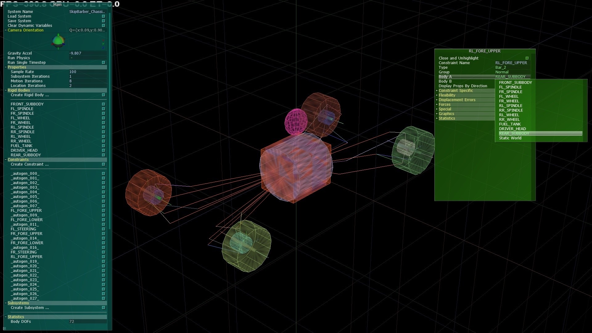
Taking shape…
You’ll need to carry on this process until you have linked all the rear suspension pieces to the REAR_SUBBODY. The front pieces are already correctly mapped.
vii) Making sure that “Offsets Stay at Local Position” is unchecked. You’ll need to re-position the front and rear sub-body co-ordinates. Select FRONT_SUBBODY, location, change the Z co-ordinate, 81cm forward (to -0.81). Now repeat the process instead moving the REAR_SUBBODY 54cm rearward (Pos Z, 0.54). Finally, select ‘Close and Unhighlight’.
3) You could either hand-edit this next part knowing the correct format, but once again, it’s easier in +pTool, so this example will be done purely in +pTool. Add a constraint of type IsoBallJoint_2, connecting as Body A ‘FRONT_SUBBODY’ and as Body B ‘REAR_SUBBODY’, let’s name it “BODY_BALLJOINT”. This defines the pivot point where the body bends and could be moved wherever you want, too. Assuming the car’s frame is fairly symmetric front to back and you don’t think the engine/driveline mounts are too much stiffness, perhaps the bending point should be exactly halfway down the wheelbase. Stiffness added from an integral mounted engine may or may not be significant, and requires some consideration with the bending point a little bit further away from that side of the chassis.
To keep it simple, put the flex right in the middle 1.35/2 = 0.675, setting the LocalOffset from FRONT_SUBBODY to (0,0,0.675) and then snap B to A. With this constraint still selected lets add some linear flex (literally stretching or shrinking the car). Although not generally a significant effect, may be included at your discretion. Set the SpringRate0=1e9 and DamperRate0=1e6. If you’d like to have the spring rates differently in each direction, you would of course, need to use constraint type AnisoBallJoint_2 instead.
4) Staying in pTool, add another constraint of type AnisoOriJoint_0, again between FRONT_SUBBODY and REAR_SUBBODY. Go ahead and change Spring Rate #2 and Damper Rate #2, which correspond to the z-axis, in other words flexing in roll (twisting the car, torsion flex). Here where you may need to back-calculate from some known roll frequency, since those are often the ones that get published. Let’s estimate a chassis roll stiffness of 17Hz. Further assuming this is exclusive of the wheels and suspension, lets say the roll inertia is 74, otherwise fully equipped. These figures are often provided with chassis frame only, running no equipment at all, in such cases the frequency is often in the realm of 50hz or more. Using the equation 2*pi*Hz = sqrt(spring_rate/inertia), the result is about 850,000 for the spring rate. Critical damping is 15,900 based on Critical Damping Ratio=DampingRate/sqrt(Mass*SpringRate)/2 and a damping ratio of about 0.1-0.4 is expected. We’ll settle on a damping rate of 6,000 for now. Now save the file out from pTool and exit (ESC key).
5) Now it’s time to try it out. Copy your file to the SkipBarber directory. You will need to replace the PhysicalModelFile line in the HDV with: UltraChassis=SkipBarber_Chassis.ini
6) Start up rF2 and load up a track. Note at this point in a dev build, it will again write out a file to UserData with updated masses and inertias and some other info about the solver (also strips out pTool-only stuff, for better or worse). Those inertias you entered before (9,9,7 & 10,10,10), represent how the total calculated inertias are split between the two bodies so a ratio of 10:9 to the rear of the car, or 10:7 for roll, you should copy these updated inertia values back to your own ‘chassis.ini’ file. Now it’s time to take your creation for a ride, at this point the driving shouldn’t be too radical, if it is, you’ve probably done something wrong! If so I direct you to the example file, and use WinMerge to spot where you might have gone wrong. Reortho= variable differences can be ignored, Name= are generally not that important except for some front suspension pieces and all rigid bodies. You’re probably looking for errors in LocalOffset’s or body connections.
Anyway, assuming things are working properly you can try and change the “BODY_ORIJOINT” spring2 and damper rate2 to something small like 100 and 0 for fun, and you should see and feel the car act much differently – you’re now driving a bit of a wet noodle and there’s no way to balance the car with anti-roll bars and springs because the chassis is so sloppy (it essentially equalizes the front and rear lateral weight transfer at all times). Of course you’ll want to undo that last change right away, it just gives an example of how the system works.
Below is how your finished vehicle should look in pTool with updated inertias from rF2.
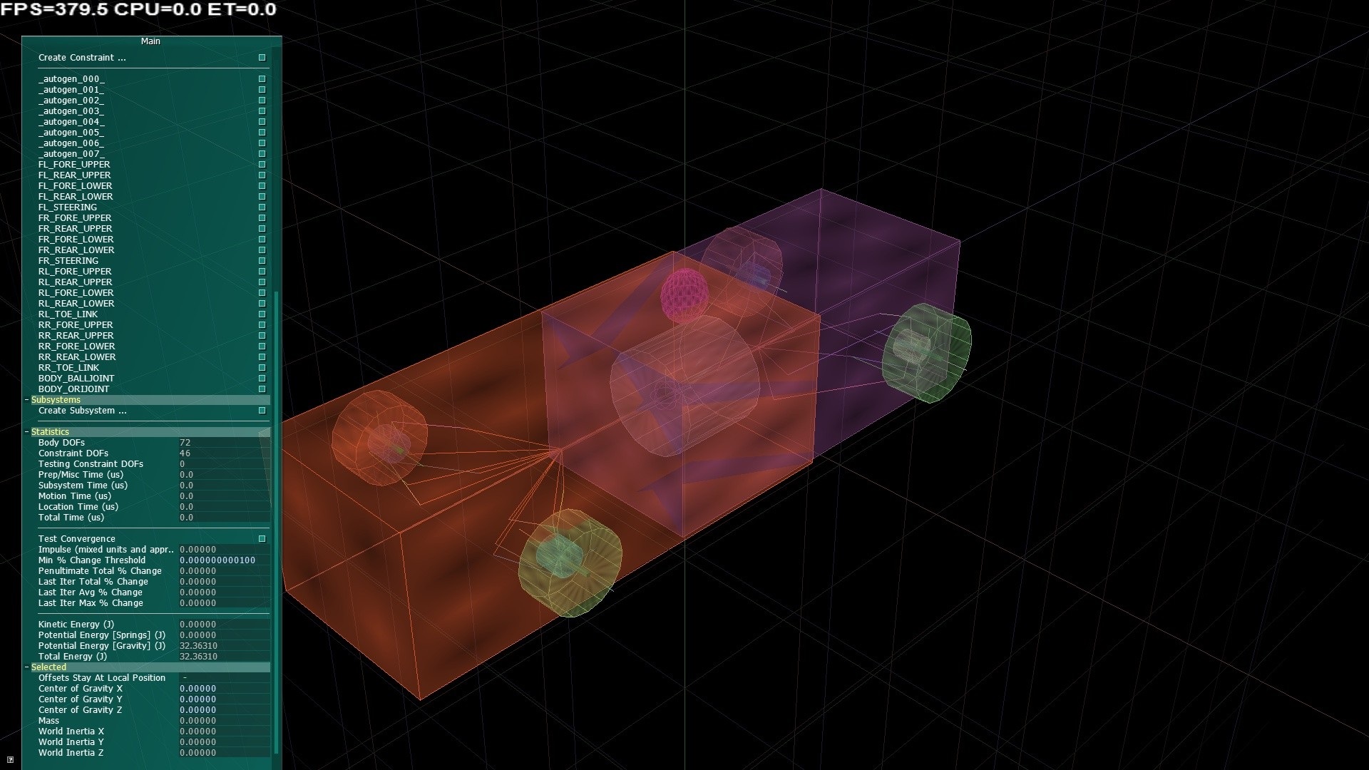
Finished product.
Some notes on the new constraint system.
If you simply convert from the old PM file to the new INI file, update the HDV and run with it, it should work nearly identically with the following known slight differences:
A) The solver will be a bit slower in this case (it has to solve one big system). However, once you break it up into front and rear sub-bodies as above, the overall solving time should be virtually identical in terms of overall performance. In the case of using four sub-bodies, performance again is very similar in real world testing when compared to the 2 body and old pm systems, perhaps performing just slightly slower. The 4 main sub-bodies approach still significantly outperforms the single body approach under the new constraint model. For this reason it’s highly recommended to keep clear of using a single body version of ultra chassis. Additionally the added complexity of 4 sub-bodies means you’ll probably want to keep clear of this as well, unless you’re really sure you know what you’re doing.
B) The fuel tank mass will start using the chassis file value rather than always forcing to 0.5. (Of course it was converted to 0.5, but if you change it, you’ll be changing the physics now; there’s still a minimum, though, of 0.05 for stability purposes.)
C) The motion ratio calculated for the springs is slightly different. This is used in a few cases for vehicle initialisation. It should actually be more accurate, but based on the differences calculated for the Camaro (less than 0.5%), it’s probably not particularly critical either way.
Some other things to note:
1) Regardless of what the chassis INI file says, LocatingSolving is not currently used. It’s too slow.
2) ‘Breakability’ stuff in the constraints don’t function in build 300. At this moment, we are not certain when it might become available, if ever.
3) The default behaviour is to distribute forces like aerodynamics to two or more subbodies them evenly. For example, even the front wing downforce is applied to the rear subbody (just way in front of it!). There are new HDV variables to control this behaviour.
By default, the fuel tank forces are computed based on the “composite” body location. Basically, using the average of the subbody locations and motions to come up with something closely resembling the old perfectly rigid body. So anyway the forces, by default, are applied equally among the subbodies.
Similarly, the air velocities for aerodynamic calc’s are based on the composite body. And again, the default is to apply the aerodynamic forces equally among the sub-bodies.
For fuel tanks, aerodynamics, and also driveline torque reactions, you can configure where they apply, with the following syntax
[GENERAL]
FuelTankForceDistrib=(0.25:front_subbody ,0.75:rear_subbody)
[FRONTWING]
FWForceDistrib=(1.0:front_subbody)
[LEFTFENDER]
FenderForceDistrib=(1.0:front_subbody) // or fl_subbody or left_subbody, as appropriate
[RIGHTFENDER]
FenderForceDistrib=(1.0:front_subbody)
[REARWING]
RWForceDistrib=(1.0:rear_subbody)
[BODYAERO]
BodyAeroForceDistrib=(0.5:front_subbody,0.5:rear_subbody)
[DIFFUSER]
DiffuserForceDistrib=(0.4:front_subbody,0.6:rear_subbody)
[DRIVELINE]
EngineTorqueDistrib=(0.05:front_subbody,0.95:rear_subbody)
ClutchTorqueDistrib=(0.02:front_subbody,0.98:rear_subbody)
GearboxTorqueDistrib=(0.01:front_subbody,0.99:rear_subbody)
DifferentialTorqueDistrib=(1:rear_subbody)
There also exists an optional offset to the *ForceDistrib=, you can append an additional :(x,y,z) to an existing body, for instance FWForceDistrib=(1.0:front_subbody:(0.0,0.0,0.5)).
This is used if you want to offset where the force is applied to a body. For example, if you wanted to reduce the torque reaction on your vehicle bodies from the fuel load you could use FuelTankForceDistrib=(0.25:front_subbody:(0,0,-0.3),0.75:rear_subbody:(0,0,0.3)), perhaps you might even want to go further than this on an older car with structural fuel tanks. Possibly the most useful operation for this would be for diffuser forces as ground effects are usually well distributed along the vehicle floor rather than applying them at a single point, which would create torques on the under-body.
All force distributions can be applied to any vehicle body, such adding some aerodynamic forces to the spindle or wheel, and negative numbers should work as well, although probably of somewhat limited use, the option remains. Ideally, the sum of each line should equal 1.0.
A note on using force distributions on wheels / spindles, at present one limitation is that in general we don’t have drag and downforce separated. So negative downforce would also mean negative drag. This behaviour might change in the future.
Finally, using *ForceDistrib with zero recognisable names will result in it falling back to default behaviour.
4) It’s also worth reading what the comments say about subsystems in the converted INI files. That is as follows.
NOTE: Subsystems, used to solve the whole system efficiently, will be created automatically if
they are not defined by the modder. The current recommendation is to allow that to happen
unless you really know what you are doing. Saving from +pTool will leave any modder-defined
subsystems in place (so that they can be re-loaded in +pTool), but conversions from the old
PM suspension files will have the single subsystem commented out (for player vehicle only,
written to UserData in Mod Mode only). In the case of an UltraChassis file without
subsystems, they will also be written for the player vehicle only to UserData in Mod Mode
with the auto-generated subsystems commented out.
5) There are some new options in the HDV called “chassis adjustments”. Arbitrarily, there are 12 new garage options available (of course, they would have to be added to the UI somewhere – in the HDV they are called “ChassisAdj00Range” thru “ChassisAdj11Range” and in the OSC they’re called “APP_SPINBOX_GARAGE_CHASSISADJ00″ also through 11). These have also been allowed for use on the existing geometry settings in the garage. Which include camber, ride height for all wheels, front/rear wheel track, weight vertical/lateral/distrib/wedge, front/rear toe-in, left/right caster, left/right track bar. Here’s how it works:
FrontToeInRange=(-0.10, 0.0, 3)
FrontToeInSetting=0
FrontToeInSpecial=(0,”noodle”,,”c(body_orijoint); springrate2=4500;damperrate2=200″)
FrontToeInSpecial=(1,”normal”,,”c(body_orijoint ); springrate2=4500000;damperrate2=20000″)
FrontToeInSpecial=(2,”‘nelastic”,,” c(body_orijoint);springrate2=4500000000;damperrate2=0 ; damperrate2+=2000000 “)
FrontToeInCaption=”roll stiffness”
While nothing has been done to stop the old geometry calibration code yet (meaning the front toe in will actually still get set to -0.10 here), the rest is actually a roll stiffness adjustment. Go to the garage Advanced page, it actually says “roll stiffness” due to the newly-available *Caption line, and you can test these values easily on track.
The special instructions are separated by semi-colons and are processed sequentially. The “c()” instruction tells us what constraint we are working on now. The other instructions are basically lines edited from the chassis.ini file, although we also allow math operations here (+=, -=, *=, /=). It’s somewhat liberal with allowing white-space, but don’t put any between the ‘c’ and ‘(‘. Some things from the chassis.ini that you cannot do are change the name of the constraint or the bodies that it connects.
A final note about “PureHinge” type. Introduced together with build 300, PureHinge has a bug that will appear with suspension damage. This will be resolved in the next public build, until then, you may use “AngularHinge” type instead which includes more DOF’s, these are not used and effectively produce a tiny hit on performance, this shouldn’t concern you too much. Still in the spirit of keeping things optimally efficient it’s recommended to use PureHinge on wheel to spindle connections, another work-around is to use invulnerability for now.
Resources:
http://beautifullyengineered.tumblr.com/post/19609093654/torsional-rigidity-a-compiled-list-of-known-specs
http://www.fisita.com/students/congress/sc08papers/f2008sc005.pdf
Our Skip Barber sample file